
| Related Topics: | ||
You can customize the appearance of a connector using the Connector Style window. Changes made in this window will apply only to the current connector; the Diagram Style window allows you to make changes to all new connectors added to the diagram as well as to all current connectors in the diagram that are using default settings.
To open the Connector Style window, select a connector and choose Format > Styles > Connector Style or double-click the connector.
![]()
For all properties on this page, the default settings, if any, are specified in the Diagram Style window on the Defaults > Connector page. You can:
Enter a caption for the connector and specify the location, text color and font used for the caption. Possible locations include:
Auto: The software will place the caption where it fits best.
Middle: The caption will be as close to the middle of the connector as possible, depending on bends in the line.
Source: The caption will be displayed where the connector meets the source block.
Destination: The caption will be displayed where the connector meets the destination block.
Hidden: The caption will not be displayed.
To use the default location, choose the Diagram Default option. To modify the text color and font, you must clear the Use Default Color and Font check box. If this check box is selected, these properties use the default settings.
Specify the connector's line style (e.g., solid, dash, etc.), thickness and color. To modify these properties, you must clear the Use Default Line Settings check box. If this check box is selected, these properties use the default settings.
Specify the kind of bend in the lines. If you select Angle or Right Angle, the Line Bend % field will be enabled. This field allows you to specify the point, in percent, at which the line will bend. For example, if you enter 50%, an angle (bend) will appear in the line at the horizontal halfway point. The available styles are shown next.
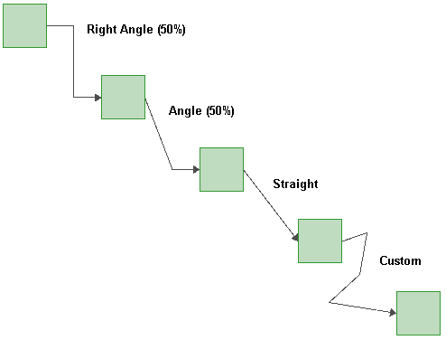
If you select Custom, you can click the connector and drag the selected point to create a bend in the line. These custom bends can be removed by clicking the connector and choosing [Diagram/Fault Tree] > Properties > Line Bend > Remove All Bend Points or, to remove a single bend point, by clicking the bend point and choosing [Diagram/Fault Tree] > Properties > Line Bend > Remove Bend Point.
To use the default setting, choose the Diagram Default option.
Specify whether or not the arrow head is displayed. To use the default setting, choose the Diagram Default option.
© 1992-2015. ReliaSoft Corporation. ALL RIGHTS RESERVED.