

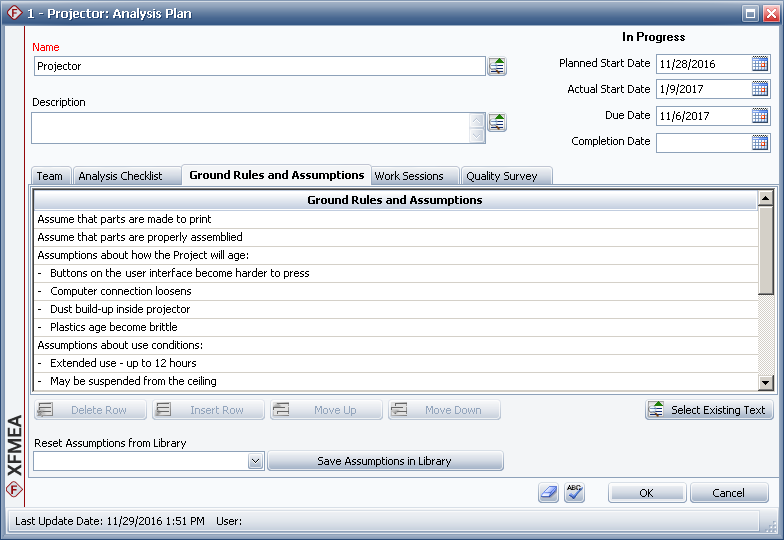
Analysis Plans allow you to keep track of team members, ground rules, estimated completion dates, scheduled work sessions and other details that will help you to plan and manage your FMEA and RCM projects.
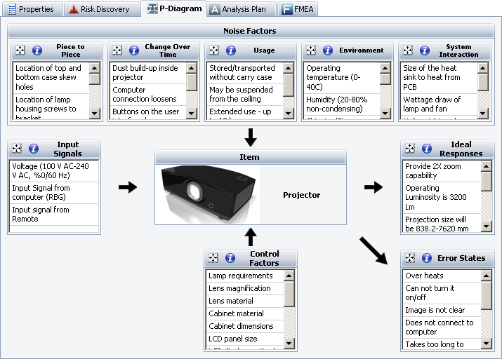
A Parameter Diagram (P-Diagram) is a structured tool that identifies the inputs from a system and relates those inputs to the desired system outputs, while considering the controlled and uncontrolled factors.
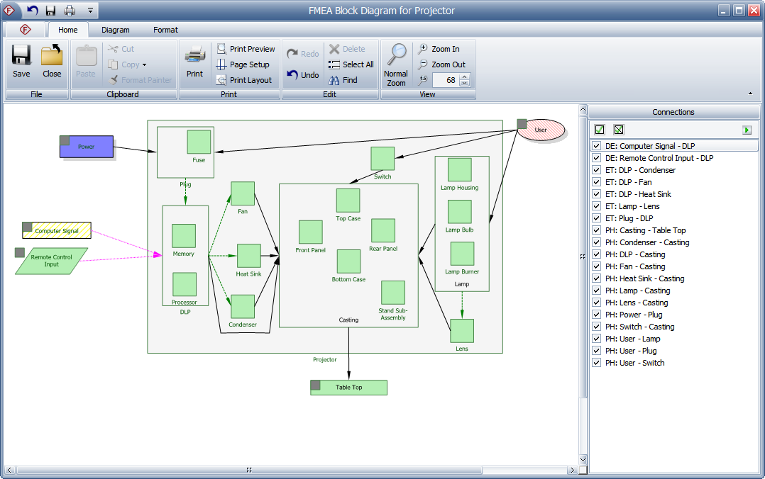
An FMEA Block Diagram visually depicts the system assembly that will be analyzed in a design FMEA. These diagrams help to define the scope of a particular analysis project and also may provide additional information that will be useful to the analysis team when they attempt to identify potential failure modes.
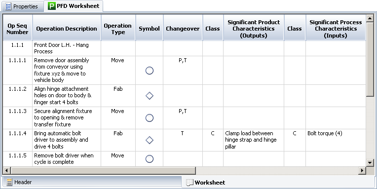
A PFD worksheet records detailed information, including process characteristics (inputs) and product characteristics (outputs), for each step of the manufacturing or assembly process. The complete PFD worksheet provides a structure for preparing process FMEAs (PFMEAs) and control plans.
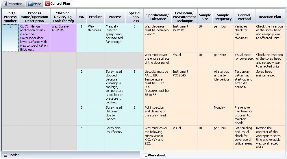
Control plans are used to track critical characteristics that must be kept in control during a manufacturing or assembly process, and record the methods for maintaining control.
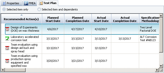
A test plan displays a list of actions that describe specific tests that need to be performed.
| Quick Tour |
| Tour Intro - Repositories & Projects - Project Properties - Using FMEAs - Using RCMs - More Analyses & Tools |
© 1992-2018. HBM Prenscia Inc. ALL RIGHTS RESERVED.
 |
E-mail Link |