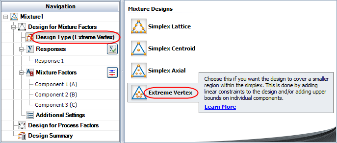

To create an extreme vertex design, follow the steps outlined next. For more general information on building designs, see Building a New Design.
Choose Home > Insert > Mixture Design to add a mixture design folio to the current project.
![]()
On the Design tab of the folio, select Design Type in the folio's navigation panel, and then select Extreme Vertex in the input panel.

If you wish to rename the folio, click the heading at the very top of the navigation panel (Mixture1 in the above example) and edit the text in the Name field on the input panel.
Define the response(s) for the design. To edit the first response, click Response1 in the navigation panel and then edit its properties on the input panel. To add a response, choose Design > Responses > Add Response.
![]()
See Adding, Removing and Editing Responses.
Define the mixture factors. Factors are defined in a similar way to defining responses. (See Adding, Removing and Editing Factors.)
Click Additional Settings in the navigation panel and specify the settings described next for the mixture factors design.
General Settings
Replicates allows you to specify the number of test samples you want to observe at each combination. In other words, the number of replicates is the number of times you want to perform the complete set of runs required by the design. Using replicates helps to separate error caused by a poor model fit from error caused by natural variation (i.e., experimental error).
Repeated Measurements allows you to specify the number of measurements to use for each test run. The mean and standard deviation of the measurements are calculated for each run, and either can be selected as the analyzed response for the experiment. This option is not available for R-DOE or designs with multiple responses.
Mixture Settings
Mixture Total allows you to specify the total amount of the mixture used for each test run.
Degree of Centroid is available only for simplex centroid and extreme vertex designs. With a degree of n, the centroid of n-dimensional space will be added to the design. (For example, the center point of a line is the centroid of a 2-dimensional space.)
Additional Runs
Center Points allows you to specify the number of center points to add to the overall design. A center point is a test run that uses a blend at the center of a space defined by the vertices.
Axial per Vertex allows you to specify the number of axial points to add for each vertex in the design (i.e., a blend with one component set to its maximum value). An axial point is a test run that uses a blend between a center point and a vertex.
Linear Constraints
Linear Constraints allow you to define limits on how the components can be combined. See Defining Linear Constraints.
Click Design for Process Factors in the navigation panel and specify whether process factors (e.g., temperature) will also be included in this design. If you choose Yes, more settings become available to specify the design for process factors. The steps for defining this part of the design are similar to those for creating a factorial design in a design folio.
Click the Build icon on the control panel to create a data sheet for the design.
![]()
© 1992-2018. HBM Prenscia Inc. ALL RIGHTS RESERVED.
 |
E-mail Link |