
The connector style settings can be defined at the diagram level in the Diagram Style window or the connector level in the Connector Style window. The connector-specific settings defined in the Connector Style window have priority over the default settings defined in the Diagram Style window for the diagram you are working with. For details on how the diagram-level and connector-level settings relate to each other, see Diagram Skins and Appearance Settings.
Note: In BlockSim process flow simulation (PFS) diagrams, connectors are considered to represent pipes. Each pipe carries a specific type of throughput flow, and there may be multiple flow types in a diagram. For these diagrams, flow types (connector styles) can also be defined at the diagram level via the Flow Types window (right-click the diagram and choose Flow Types). This window works similarly to the Diagram Style window, and connector-specific settings also have priority over settings defined in the Flow Types window.
Diagram Level
To open the Diagram Style window, right-click the diagram (not blocks) and choose Diagram Style.
Connector Level
To open the Connector Style window, select one or more connectors, right-click one of the connectors then choose Connector Style.
Note that if you are using the this window, you must clear the Use Default check boxes in order to modify some settings.
Line Settings: Specify the connector's line style (e.g., solid, dash, etc.), thickness and color.
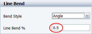
Line Bend and Arrows: Use the Line Bend drop-down list to specify the kind of bend that you want in the lines. Note that if you select Angle or Right Angle, the Line Bend % field will be enabled. This field allows you to specify the point, in percent, at which the line will bend. For example, if you enter 0.5 (50%), an angle (bend) will appear in the line at the horizontal halfway point.

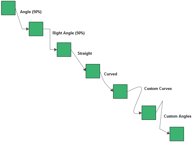
The available bend styles are shown next.

Specify the location, text color and font used for the caption. The caption text for a connector is entered in the Connector Style window.

Note that in BlockSim/RENO, you cannot enter caption text for connectors used in phase diagrams, RENO flowcharts and Markov diagrams.
When you are working with a BlockSim PFS diagram, the Diagram Style window and the Flow Types window also require you to specify a name (for future reference) and an abbreviation (used in the diagram, plots and results) for each flow type.
To use the diagram style settings again, in the Connector Style window, choose Diagram Default from the drop-down lists and select the Use Default check boxes.
© 1992-2019. HBM Prenscia Inc. ALL RIGHTS RESERVED.
| E-mail Link |