
Connectors represent the flow of the process or system being diagrammed, and the lines contain information about the relationship between the specific source and destination blocks that they connect. In BlockSim process flow simulation (PFS) diagrams, connectors are considered to represent pipes. Each pipe carries a specific type of throughput flow, and there may be multiple flow types in a diagram.
To add a connector between blocks, you can:
Right-click the diagram (not blocks) and choose Connect Blocks or choose the command in the ribbon.
Hold down the ALT key.
In PFS diagrams, use the down arrow on the Connect Blocks ribbon command to specify which flow type you are currently adding before using either of these methods.
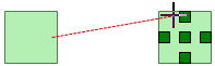
In both methods, the pointer will change to display small crosshairs. Click the source block, hold down the left mouse button and drag a line from the source block to the destination block. When the crosshairs are located over the connection point box, release the mouse button to create a connector.
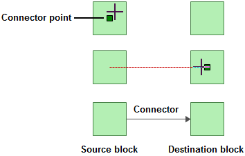
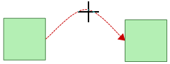
Note that existing connectors can be dragged to different destination blocks, if needed. Also note that the curved, custom curve and custom angled connector types give you the option to connect to the top or bottom of a block, if desired. When this option is available, the blocks will show additional connection point boxes when you create or move a connector.
To stop adding connectors and return the pointer to its normal mode, release the ALT key or click inside the diagram.
Tip: If you do not click the diagram or clear the Connect Blocks option to return the pointer to its normal mode, you will not be able to perform certain other activities, such as moving or deleting blocks. If you are experiencing difficulties with the application, make sure that the pointer is in its normal mode.
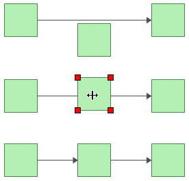
RBDs, PFS diagrams, Markov diagrams and RENO flowcharts allow you to insert a block into the flow of the diagram without having to delete and add connectors. Simply drag an unconnected block onto an existing connector. When the pointer changes to a double-headed arrow, drop the block to split the existing connector and insert the block.
There are several types of connector that can be used in a diagram. The simplest is a straight line but there are options for adding line bends to create curved or angled lines. For details about available connector styles and defining preferences, see Connector Style Settings.
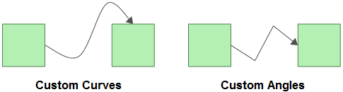
When using curved, custom curve or custom angle connectors, you can choose the location where they connect to the blocks (top, middle or bottom) and add one or more bends to the line. These options can be used separately or in combination.
To add or modify line bends:
Curved connectors have a single bend point in the center of the connector. To change the angle, click and drag the point to the desired location.
For custom curve and custom angle connectors, add line bend(s) by clicking anywhere on the connector and dragging the selected point to the desired location.
These custom bends can be removed by right-clicking the connector and choosing Remove all Bend Points or, to remove a single bend point, by right-clicking the bend point and choosing Remove Bend Point.
© 1992-2019. HBM Prenscia Inc. ALL RIGHTS RESERVED.
| E-mail Link |