
|
Creating Diagrams from Synthesis Data |
||

You can create RBDs that represent items from analyses performed in the current project in Xfmea/RCM++/RBI in order to perform system maintainability and availability analysis for these items. To do this, choose Insert > Build from Synthesis > Build RBDs and FTs from Synthesis.
![]()
The Build RBDs and FTs from Synthesis window consists of two steps. When the window opens, you will see the Options step. Specify that you want to use RCM++/Xfmea/RBI as the data source in the Synthesis Element to Build From area. (You can use data from the Synthesis versions of RCM++, Xfmea or RBI.)
In the Diagram Type area:
Specify whether you want to represent the imported items' reliability-wise relationships using fault trees, RBDs or a hybrid of the two. If you choose the Hybrid option, all systems will be imported as RBDs, while FMEA information will be imported as fault trees.
Choose whether you want the new diagrams to be analytical diagrams or simulation diagrams.
If you select the Create folders check box in this area, each diagram will be added to the current project explorer within its own folder under the Fault Trees or RBDs folder. The new folders will be arranged hierarchically in the same way as the information in the original analysis, thus making their hierarchical relationship visually apparent within the current project explorer.
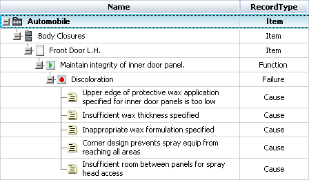
The reliability information for each branch of the FMRA hierarchy is taken from the highest-level item for which reliability is specifically defined, rather than inherited. For example, imagine that you are importing from the following hierarchy and creating fault trees from the information:
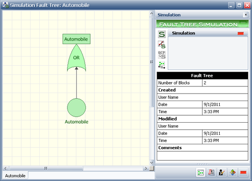
If a URD is assigned to the Automobile item, then only the following diagram will be created:
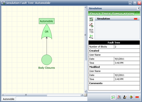
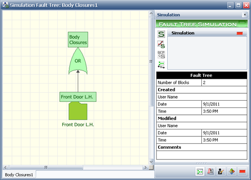
If a URD is assigned to the Body Closures item and the Automobile item is set to inherit its reliability characteristics from that, then the following diagram will be created:
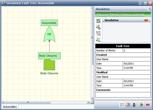
If a URD is assigned to the Front Door L.H. item and the Automobile and Body Closures items are set to inherit their reliability characteristics, then the following diagrams will be created:

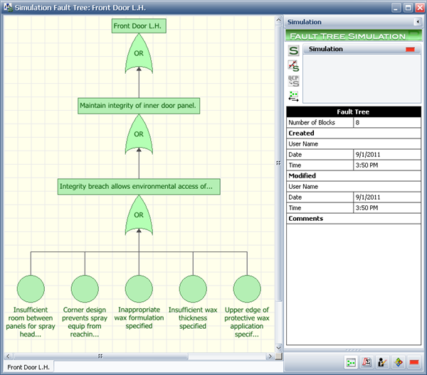
Finally, if all items are set to inherit their reliability characteristics and URDs are assigned only to the causes in the FMEA for the Front Door L.H. item, then the following diagrams will be created:
If you are creating RBDs or a hybrid of RBDs and fault trees, the Subdiagram Grouping area will be available. The options in this area allow you to control which levels of analysis will be represented by subdiagrams. For example, consider the final case above, where all system hierarchy items are set to inherit their reliability characteristics and URDs are assigned only to the causes in the FMEA for the Front Door L.H. item.
If you are creating RBDs, your choices in the Subdiagram Grouping area will determine how the system and reliability information is represented across diagrams, as follows:
If you select Create system-level diagrams, then a diagram will be created for each item in the system hierarchy. The top level (i.e., Automobile) diagram will contain a subdiagram block representing the next level item (i.e., Body Closures) and so on. The diagram representing the lowest level in the system hierarchy (i.e., Front Door L.H.) will contain the FMEA information. This may be shown as causes or additional levels of subdiagrams may be included to represent the function and/or failure, depending on your choices for the next two options.
If you select Create subdiagrams for functions, then the function level of the FMEA will be represented by a diagram. Note that if you select this check box but do not choose to create subdiagrams for items in the system hierarchy, then the function diagram will be the top level diagram.
If you select Create subdiagrams for failures, then the failure level of the FMEA will be represented by a diagram. Note that if you select this check box but do not choose to create subdiagrams for items in the system hierarchy, then the failure diagram will be the top level diagram.
By combining these options, you can control the levels that are represented in the RBD(s) created. Bear in mind that, as with fault trees, the reliability information for each branch of the FMRA hierarchy is taken from the highest-level item for which reliability is specifically defined, rather than inherited. This is true not only for system hierarchy items, but also for FMEA records. For example, if reliability is defined for a function, that function will be shown as a block in the resulting RBD and no subdiagram will be created for it (i.e., any failures and causes assigned to the functions will not be imported, as they are not relevant to the reliability).
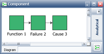
The Create subdiagrams for functions and Create subdiagrams for failures check boxes control only how information is organized, not what information is imported. All items with reliability information defined will be imported, regardless of your selections for these check boxes. For example, consider a component with an FMEA that includes three functions, each of which has a failure and a cause defined. Its FMRA is shown next.
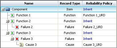
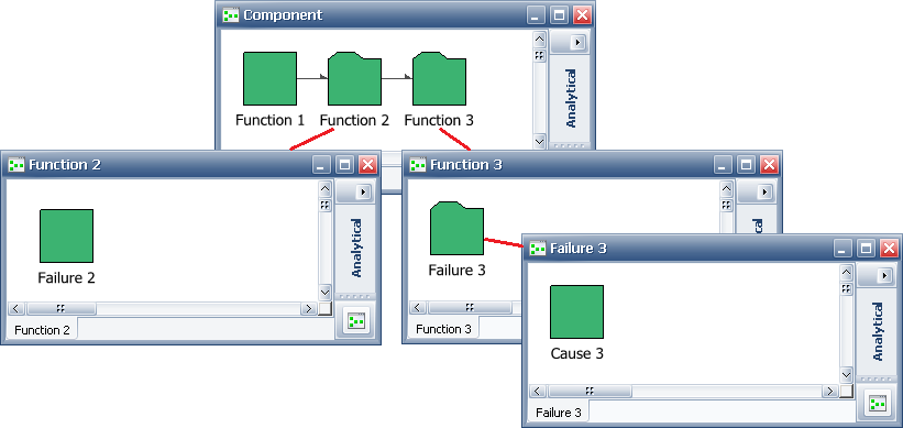
As you can see, the reliability is defined at the function level for Function 1, at the failure level for Failure 2 and at the cause level for Cause 3. If you imported this configuration with both the Create subdiagrams for functions and Create subdiagrams for failures check boxes selected, you would get the diagrams shown next.
On the other hand, if you imported the same configuration with neither of the two check boxes selected, you would get the following diagram:
If you are creating a hybrid of RBDs and fault trees, only the Create subdiagrams for functions check box will be available. In this case, system-level diagrams are always created. Your selection in this area determines whether the fault trees are created at the function level or at the failure level.
When creating either fault trees or RBDs, you can use the Overridden Items area to import items that would normally not be imported.
Select the Import items even though overridden by higher level definition check box to allow you to import lower-level items even if a higher-level item has defined reliability characteristics. Selecting this option causes the reliability of the higher-level item(s) to be set to inherit from the lower-level item(s) for the purposes of the import. The settings will not be changed in the original analysis.
Select the Import items regardless of reliability policy check box to allow you to import items even if they are set to inherit their reliability characteristics and no reliability characteristics are defined for any item below them. Selecting this option can cause empty diagrams to be created.
Click the Next button to view the Hierarchical Representation step, which displays a hierarchical view that corresponds to the diagram(s) that will be created. You can select or clear items in this tree to specify whether they will be included in the diagram(s). If the tree does not correspond to the diagram(s) you have in mind, you can click the Back button to return to the Options step and try again. Otherwise, click OK to create the diagram(s).
© 1992-2017. HBM Prenscia Inc. ALL RIGHTS RESERVED.
 |
E-mail Link |