
 |
||
By default, the records in an FMRA are assumed to have a reliability-wise series configuration. In other words, if any failure mode occurs or any component fails, then the entire system fails. However, you can use BlockSim's FMRA diagrams to represent more complex configurations.
To do this, choose FMRA > Refresh > Synchronize FMRA to refresh the FMRA and create the associated diagrams and blocks.
![]()
Note the following about FMRA synchronization:
Changes that are made in BlockSim are synchronized and propagated to Xfmea/RCM++/RBI automatically, although you may need to refresh the view to see them (View > Refresh).
When records are added to the current FMRA in Xfmea/RCM++/RBI, they will not be displayed in BlockSim's FMRA hierarchy until you synchronize the FMRA (FMRA > Refresh > Synchronize FMRA). This will refresh the FMRA hierarchy and create the associated diagrams and blocks. Depending on the changes that were made in Xfmea/RCM++/RBI, this may affect your FMRA diagrams.
If you no longer wish to synchronize the FMRA with BlockSim diagrams, you can choose View > FMRA > Disassociate FMRA to delete all of the FMRA diagrams and close the FMRA view. You can resynchronize at any time.
It is important to note that the diagrams that you work with from within the FMRA are distinct from the other diagrams in BlockSim’s current project explorer. FMRA diagrams relate to the analysis being performed in the project using Xfmea/RCM++/RBI. They are accessible only via the FMRA view, while all other diagrams are accessible only from the Standard tab of BlockSim’s current project explorer.
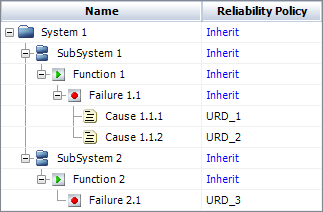
Each record in the FMRA hierarchy represents a reliability block diagram, with the exception of the lowest-level record in each branch, which represents a block in the parent diagram. The levels of the hierarchy are expressed using subdiagrams. For example, consider the FMRA hierarchy shown next.
Now, let's look at the branch of the FMRA that begins with SubSystem 1. The associated FMRA diagrams are:
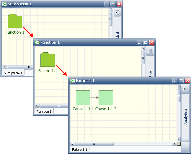
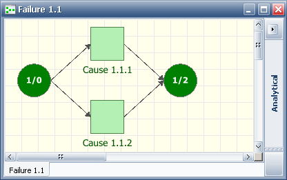
As you can see, the causes are assumed to be in a series configuration, as is the case with all reliability-wise configurations built in Xfmea/RCM++/RBI. Working with the FMRA in BlockSim allows you to change the reliability-wise configuration. For instance, let's imagine that the causes are actually in a parallel configuration—in other words, the item will not fail if only Cause 1.1.1 happens OR only Cause 1.1.2 occurs, but the item will fail if both occur. To represent this, you would change the Failure 1.1 diagram as follows (with the first node acting as a starter block):
By default, the FMRA diagrams are created as analytical diagrams. You can choose FMRA > Inheritance > Toggle Diagram Type to change them to simulation diagrams, or to change simulation diagrams to analytical ones. This command changes all of the FMRA diagrams in the project; you cannot have both analytical and simulation FMRA diagrams in the same project.
Like any other RBD, the diagram type affects the available functionality, both in terms of configuration and results. For instance, maintenance groups can be assigned only in simulation RBDs. You can analyze or simulate an FMRA diagram just as you would any other RBD, and can generate plots and QCP results for each diagram. You also can perform analytical calculations or simulation at the FMRA level.
© 1992-2017. HBM Prenscia Inc. ALL RIGHTS RESERVED.
 |
E-mail Link |