
| Related Topics: | ||
|
Background: FMEA and Related Analyses |
||
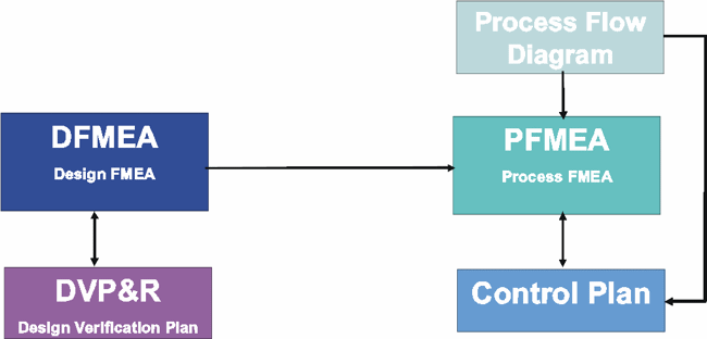
Within the automotive industry and some other industries, practitioners have integrated FMEA with other quality planning efforts. As shown in the following diagram, this might include:
Transferring information from the design FMEA to the Design Verification Plan (DVP&R).
Transferring information from the design FMEA to the process FMEA.
Transferring information from the Process Flow Diagram to the process FMEA.
Transferring information from the process FMEA to the Process Control Plan.

These integrations are described briefly in the sections that follow.
The design verification plan and report (DVP&R) is a worksheet that is used to track the progress of design verification tests. The lessons learned from the DFMEA can be a valuable input to the DVP&R (and vice-versa). For example: if the design FMEA indicates that Part X will fail if the incorrect wax thickness is applied for protection, then it may be appropriate to add a test to the design verification plan for determining the optimum wax thickness to be applied.
Tip: The DVP&R Analysis in Xfmea provides a configurable worksheet for design verification planning and reporting, including the ability to synchronize the DVP&R with information transferred from an existing FMEA.
The lessons learned from a design FMEA also can be a valuable input to the process FMEA. Analysts may wish to transfer relevant information between analyses, where:
Causes in the DFMEA can become failures in the PFMEA.
Failures in the DFMEA can become effects in the PFMEA.
For example, if the design FMEA indicates that Part X will leak if the hole diameter is too wide then the design FMEA will consider whether the specified hole diameter is appropriate while the process FMEA will consider aspects of the manufacturing process that may cause the hole diameter to vary from the specification.
DFMEA: Failure = Leak; Cause = Hole too wide.
PFMEA: Failure = Hole too wide; Effect = Leak.
Causes = ?
Controls = ?
Actions = ?
Tip: The Transfer Projects feature in Xfmea allows you to transfer selected data from an existing design FMEA to a new process FMEA.
As described in Determining the Scope, the process flow diagram (PFD) provides a logical, visual depiction of the process that is being analyzed and such diagrams can be useful to determine the steps in the process and the critical characteristics that will be analyzed in the PFMEA.
In addition, the process control plan (PCP) describes the actions that are required at each phase of the process to ensure that all process outputs will be in a state of control. The process flow diagram and the lessons learned from a process FMEA can be a valuable input to the process control plan. The linkages between these documents might be applied as follows:
Operation # and Description flow from the Process Flow Diagram to the PFMEA to the control plan.
Significant Product Characteristics (and Classifications) contribute to the definition of failure modes and/or causes in the PFMEA. They also flow to the control plan.
Current Controls flow from the PFMEA to the control plan.
Tip: The control plan analysis in Xfmea provides a configurable worksheet for process control planning, including the ability to synchronize the Control Plan with information transferred from an existing FMEA.
© 1992-2013. ReliaSoft Corporation. ALL RIGHTS RESERVED.