![]()
![]()
Home > DOE Design Folios > Mixture Designs > Extreme Vertex Designs > Defining Linear Constraints
Unlike component bounds, which put limits on individual component amounts, linear constraints allow you to place limits on combinations of components. As an example, if you have three components in your experiment (C1, C2 and C3), the following two limits would be linear constraints:
The combined amount of C1 and C2 in any blend must be at least 0.5 grams.
In any blend, the amount of C3 must be at least twice the amount of C2.
When you're creating an extreme vertex design, constraints like these are defined by opening the Linear Constraints window. To do this, click the Additional Settings heading on the navigation panel, and then click the [+] icon under Linear Constraints. To remove a constraint, click the [-] icon next to it.
Each row in the Linear Constraints window represents an equation that defines a single constraint. The first and last columns represent lower/upper bounds of the constraint, and the middle columns represent the coefficients of each component in the blend (the column headers show the abbreviated factor names). If a constraint lacks a lower or upper bound, or if there certain components that are not considered, you can leave those cells blank.
Consider the two example constraints above. These constraints could be defined as shown next.
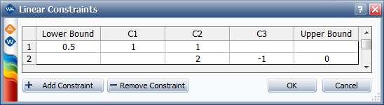
According to the first constraint, the combined amount of C1 and C2 must be at least 0.5. In other words:
0.5 <= C1 + C2
So 0.5 is entered for the lower bound, and 1 is entered for the coefficients of C1 and C2.
The second constraint can be expressed as follows.
2*C2 <= C3
In other words, C3 must be at least double the amount of C2. This is equivalent to the following:
2*C2 - C3 <= 0
So 2 and -1 are entered for the coefficients of C2 and C3, and 0 is entered for the upper bound.
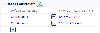
After you click OK, the constraints are displayed in the folio as shown next. To edit a constraint, just click the blue equation to re-open the Linear Constraints window.
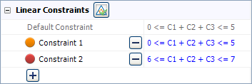
To determine whether you have entered any incompatible or unnecessary linear constraints (i.e., constraints that rule out all blends, or which do not impose any new limits beyond those already defined), click the Validate Constraints icon in the additional settings.
Colored dots will appear next to any problematic constraints. Red dots represent incompatible constraints, and orange dots represent unnecessary ones. For example, Constraint 1 below is unnecessary because it is identical to the default constraint. And Constraint 2 is incompatible with Constraint 1 because no blend can have an amount that is both at most 5 (Constraint 1) and at least 6 (Constraint 2).
Note: Information on the number of runs in the Design Information area of the control panel and in the Design Summary will not be available until you have validated the constraints.
© 1992-2017. HBM Prenscia Inc. ALL RIGHTS RESERVED.
 |
E-mail Link |