
| Related Topics: | ||
RCM++ allows you to create a process flow diagram for any item in the system hierarchy. Process flow diagrams are high level charts that help you to visualize the steps that a product goes through in a manufacturing or assembly process.
Tip: If you want to use the process flow diagram as a starting point for preparing process FMEAs (PFMEAs) or control plans, then the PFD worksheet may be a more appropriate tool. The PFD worksheet integrates the chart into a worksheet that records more detailed information about each step in the process and it allows you to synchronize the relevant information with the PFMEA or control plan analysis. See PFD Worksheets.
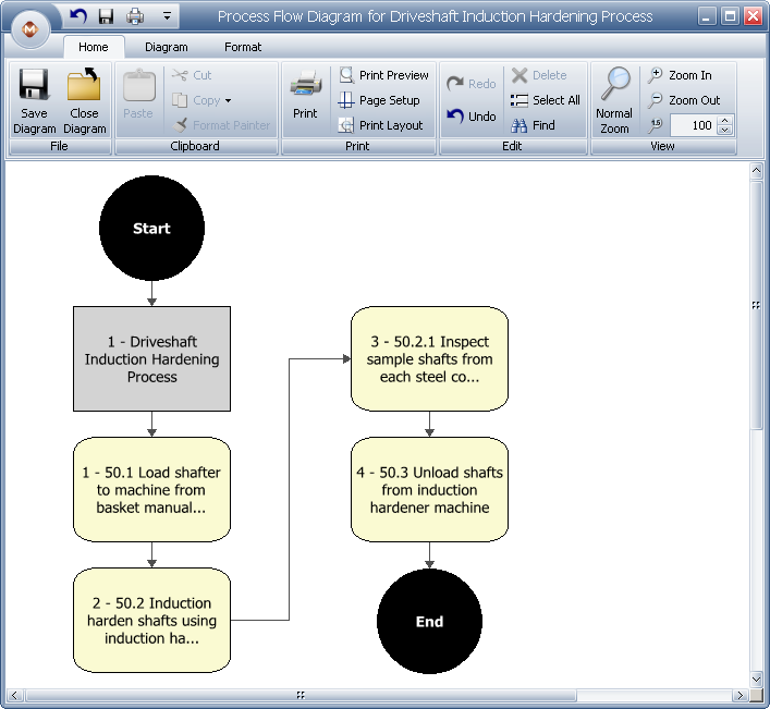
An example of a process flow diagram is shown next.
To create a process flow diagram, select an item in the System panel then choose System Hierarchy > Diagrams > Process Flow Diagram. You can also right-click the item and choose Diagrams > Process Flow Diagram.
![]()
When you are creating a new process flow diagram, the Create Process Flow Diagram window will appear, which gives you the option to start with a blank diagram or generate blocks based on the item’s FMEA or control plan.
Based on system hierarchy creates a process flow diagram based on the item that is currently selected in the System panel. If the item has any sub-items, those sub-items will also be added to the diagram.
Based on system hierarchy and FMEA functions creates a process flow diagram based on the FMEAs of the item that is currently selected in the System panel. Each function in the existing FMEA will be transferred to a block in the process flow diagram. If the item has any sub-items, those sub-items and the FMEA functions of those sub-items if any, will also be added to the diagram.
Based on control plan creates a process flow diagram based on the existing control plan associated with the item that is currently selected in the System panel. Each Process Name/Operation Description in the existing control plan will be transferred to a block in the process flow diagram.
Tip: If a diagram has already been created, you will be prompted to either open the existing diagram, delete the previously saved diagram or create a new diagram that replaces the existing version.
When you close the diagram, a window will appear asking if you want to save the diagram.
© 1992-2013. ReliaSoft Corporation. ALL RIGHTS RESERVED.