
| Related Topics: | ||
Connectors in RCM++ represent either the flow of the process or system being diagrammed, or represent the relationships between the causes, effects and failures in an FMEA. The lines contain information about the relationship between the specific source and destination blocks that they connect.
To create a connector between blocks, you can:
Choose Diagram > Settings > Connect Blocks.
![]()
Hold down the ALT key while selecting the source block and then drag a line to the destination block.
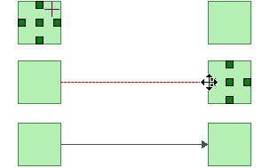
In both methods, the cursor will change to display small crosshairs. Click the source block, hold down the left mouse button and drag a line from the source block to the destination block. When the crosshairs are located above the destination block, release the mouse button to create a connector.
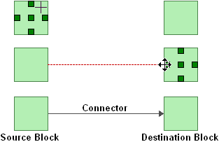
The location where the connector attaches to each block is determined by your selection in the Automatic Connection Preference field on the Connector Handles and Indicators page of the Diagram Style window. If the field is set to Left-Right, the connector will attach to the sides of the blocks; if it is set to Top-Bottom, the connector will attach to the top and bottom of the blocks. If No Preference is chosen, the connector will attach to the closest edges.
If you have selected Custom in the Bend Style field on the Connector page of the Diagram Style window, then when you are connecting blocks, five boxes will appear on each block that you point to. These boxes are connection points. You can click a connection point to use it as the location where the connector connects to the block. This allows you to draw connectors to and from any side of a block. The center connection point places the line using the default routing scheme, as defined in the Automatic Connection Preference field on the Connector Handles and Indicators page of the Diagram Style window.
Note that once you have added a connector that uses the Custom bend style, you can click the connector and drag the selected point to create a bend in the line. These custom bends can be removed by clicking the connector and choosing Diagram > Properties > Line Bend > Remove All Bend Points or, to remove a single bend point, by clicking the bend point and choosing Diagram > Properties > Line Bend > Remove Bend Point.
To stop adding connectors and return the cursor to its normal mode, release the ALT key or right-click the diagram or clear the Connect Blocks option by choosing the command again.
Tip: If you do not right-click the diagram or clear the Connect Blocks option to return the cursor to its normal mode, you will not be able to perform certain activities in RCM++, such as moving or deleting blocks. If you are experiencing difficulties with the software, make sure that the cursor is in its normal mode.
© 1992-2013. ReliaSoft Corporation. ALL RIGHTS RESERVED.