

The control panel associated with RENO flowcharts consists of multiple pages, each containing options for performing particular tasks. This topic focuses on the Simulation page of the RENO flowchart control panel, which contains most of the tools you will need to simulate a diagram. For more information about the control panel in general, see Control Panels.
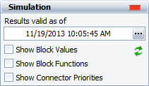
The Simulation area displays the status and results of the simulation.

Status If the light is green, then the simulation has been performed. If the light is red, then the simulation has not been performed. A simulated diagram will remain in the simulated state unless a change is made to the structure of the diagram (e.g., a block is added, a connector is removed, etc.).
Show Simulation Details (...) displays the most recently generated simulation results in the Results Explorer.
Select the Show Block Values check box to display the most recent value for each block (except for reset blocks and subchart blocks) at the end of the last simulation in the block's description. The location and appearance of the block description can be changed via the Diagram Style window or the Block Style window. (For information on modifying appearance settings, see Diagram Skins and Appearance Settings.) If you have made any changes to the flowchart since the last simulation, no values will be displayed.
To perform a single simulation of the flowchart using the seed that is currently specified in the RENO Simulation window, click the Update Block Values icon.
![]()
Select the Show Block Functions check box to display information about the function the block performs in the block's description. Specifically, for each block type, the following will be shown. (For block types not shown in this list, nothing is displayed.)
Flowchart standard blocks: equation
Result storage blocks: result type (e.g., average, sum, etc.)
Conditional blocks: condition (e.g., =, >, etc.)
Logic gates: gate type (e.g., AND, OR, etc.)
Summing gates: operation
Go-to-flag blocks: the target flag marker
Counter blocks: counter type (i.e., when the counter resets)
Subchart blocks: the flowchart that is being used as a subchart
Select the Show Connector Priorities check box to display the order of execution of the outgoing paths from each block. This order is based on the connector priority and can be changed by selecting a connector and then choosing Flowchart > Selection > Connector Priority.
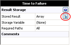
The Information area displays information about the diagram or the currently selected block. If no block is selected in the diagram, the Information area displays the number of blocks in the diagram and information about the diagram creation and last modification. If a block is selected in the diagram, it displays a subset of the properties found in the Block Properties window. If you have selected a result storage block of type array in a simulated flowchart, you can click the Transfer Data to Weibull++ icon in the Information area of the control panel to create a Weibull++ life data folio containing the stored values.

This area also offers a Comments field; click the field heading to enter comments. For blocks, these comments are also accessible in the Identifiers properties in the Block Properties window.
The Tools area on the left side of the control panel gives you quick access to the tools you will need to analyze the diagram and generate additional results.
![]() Simulate opens the RENO Simulation window, which allows you to specify simulation settings for the current diagram and run the simulation.
Simulate opens the RENO Simulation window, which allows you to specify simulation settings for the current diagram and run the simulation.
![]() Plot creates a plot based on the simulation results. Clicking the Plot icon before the diagram has been simulated will automatically perform the simulation and then plot the data.
Plot creates a plot based on the simulation results. Clicking the Plot icon before the diagram has been simulated will automatically perform the simulation and then plot the data.
![]() Debug opens the RENO Simulation Debugger, which allows you to trace and examine the output of a flowchart by running a step-by-step simulation through each block.
Debug opens the RENO Simulation Debugger, which allows you to trace and examine the output of a flowchart by running a step-by-step simulation through each block.
© 1992-2019. HBM Prenscia Inc. ALL RIGHTS RESERVED.
| E-mail Link |