

The two possible outcomes of an operational phase block are modeled using success and failure paths. Node blocks and stop blocks are provided to allow you to build configurations that are both accurate and readable.
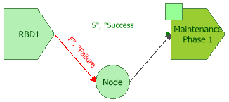
The purpose of a node block is simply to enable configurations that would otherwise not be possible due to limitations on connecting blocks. For example, consider an instance where maintenance is scheduled to be performed after the operational phase has completed successfully, and if a failure occurs during simulation, that maintenance will take place upon failure. In this case, the operational phase block's success and failure outcomes are identical. Success paths and failure paths cannot be identical in phase diagrams, however, so you would model this configuration in one of two ways:
If the operational phase stops upon failure of the block and the simulation moves to the next phase along the success path, you would use a node block to model this configuration, as shown next.
If the operational phase continues for the specified duration despite failure and the simulation then moves to the next phase along the success path, you would simply not create a failure path. If there is only a success path, then upon system failure during this phase, the corrective maintenance specified begins and the time to restore the system is part of the operational phase's time. In other words, the repairs continue in the operational phase until the system is up again. If the repairs are not completed before the phase ends, the repairs continue into the next phase. Thus, in this case, the duration of an operational phase is not affected by a system failure. For example, consider a production line operating in two phases: a day shift and a night shift. A failure occurs in the day shift that renders the production line non-operational. Repair of the production line begins immediately and continues beyond the day shift. The production line is back up after midnight. In this case, the repair of the production line exhausts all of the duration of the day shift phase from the time of the failure to the end of the phase. Some part of the night shift phase is also exhausted.
Node blocks can have unlimited incoming connections and a single outgoing connection.
Node blocks have no properties other than their block name. Each block is given a default name that is determined based on the default naming criteria established for the current database (see Default Name Formats window). You can replace this with your own name of up to 150 characters, if desired.
Stop blocks indicate that the simulation of the mission ends. A new simulation may then begin, if applicable. This is useful in situations where maintenance is not possible upon failure.
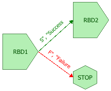
Stop blocks can have unlimited incoming connections. No outgoing connections can be defined for stop blocks.
© 1992-2018. HBM Prenscia Inc. ALL RIGHTS RESERVED.
 |
E-mail Link |