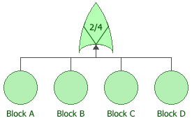


Voting gates allow you to represent a scenario in which the output event occurs if some quantity (k) or more of the input events occur. In system reliability, this implies that if any k-out-of-n components fail (input events), the system will fail (output event). In a reliability block diagram, this is similar to a k-out-of-n parallel configuration. That is, a fault tree looks at the k-out-of-n failures for the system failure while an RBD looks at the k-out-of-n successes for system success.
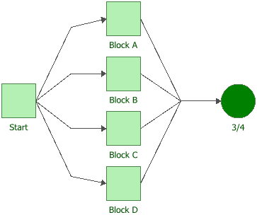
The next two figures show both the fault tree diagram and reliability block diagram representation of a system with four components, A, B, C and D, in which the system fails if any two of the components fail. In a fault tree, this is modeled using a voting gate with a vote number of 2.

This is represented by the RBD shown next. In this configuration, the system will not fail if three out of four components are operating, but will fail if more than one fails.

To configure a voting gate, in addition to the common block properties, you will need to use the Vote number field to specify the number of input events required to trigger the output event.
© 1992-2017. HBM Prenscia Inc. ALL RIGHTS RESERVED.
 |
E-mail Link |